One of the blogs that I follow is Christopher Schwarz’s who is an editor for Popular Woodworking Magazine. Christopher is crazy for woodworking hand tools and focuses on their use, history, and those who used them in the past. About a month ago he posted on a Hand Cranked Grinder http://www.popularwoodworking.com/article/using-a-hand-cranked-grinder I saw his post and realized two things: that they make such a thing and that I need one! I’d been wanting a grinder for a while but don’t want one of the ones from the home improvement stores. So, I figured I’d give one of these a try. A quick trip to ebay showed that they’re really inexpensive which is always a plus. I found one several ones in working condition but I liked the raised lettering on this one. $5 plus shipping had this arrive at my door.

This is the “front” of the grinder. You can see the knob for the clamp in the lower left and the bracket for the tool rest sticking out of the left side. The seller forgot the tool rest but has already dropped it in the mail to me so it isn’t pictured here. The handle is detached laying in the background but is normally attached to the axle sticking out of the center. Here’s a picture for another angle.

In the lower left of this picture you can see the axle that the grinding wheel would mount on between the two flanges. It came with a grinding wheel but it’s junk as it has been extremely well used. From this view you can also see how it works. It has two gear in it resulting in the grinding wheel spinning at a much faster rate that you’re cranking. There is also supposed to be a cover over the gears but it is missing so I’ll have to fab something up later on.
Now I could use it this way without cleaning it up but where’s the fun in that? To clean it up we’ll first need to disassemble it.
The first step was to remove the nut and flanges (black arrow), tool rest and bolts (yellow arrows), and the two screws that don’t seem to do anything (red arrows). The nut (black arrow) was a left hand thread so that it doesn’t loosen as you grind. 99% of the screws you’ll encounter in the world are right hand thread and fit the rhyme we all know.

Next, I removed the cotter pin (shown in first pic) from wheel axle (yellow arrow). This can be done by straightening it and pulling out with needle nose pliers. I then clamped it up in my large vise with wood to keep it from rotating and protect the housing. The axle was then driven out the “back” of the housing using a ball peen hammer and pin punch tapping lightly. You want to be sure to catch the axle so it doesn’t smack the concrete below.

From here, the crank handle axle needed to be removed. This ended up being the toughest part of disassembly. To connect the axle to the large gear it could have been press fit or there could be set screws holding it on. Inspection with a flash light showed that it has two square headed, slotted screws. They’re shown with a yellow and red box. As you can see, they were kinda gunked up with sludge and rust. With old stuff that’s stuck together you want to do everything you can not to strip the hardware as it makes things much harder.
There are a couple of steps you can take to ensure your success. The first is to use a penetrant that helps loosen things that are rusted together (PB Blaster is what I use) and give it time to work. The second is to use a screwdriver that fits the screw head well. Yes, there’s a difference. I had a couple of screwdriver to use that were the same width but had different tip thicknesses. The one with the thicker tip fit the screw slot much better reducing the chance that I’d mess up the head. Third make sure that the screwdriver is as straight as possible on the screw head. Forth, push the screwdriver down into the screw as you try to turn it to reduce the chance it’ll cam out. It goes without saying, but you want to make sure you’re turning the right direction.
So, I first shot it with a lot of PB Blaster and then gave it about 30 minutes. Then, I shot it some more and waited again. I used the best fitting screwdriver and tapped on the end of it with a hammer while trying to twist the screwdriver. The screw in the yellow box was nice and came out pretty easily. The one in the red was a pain as it was trying to strip but it eventually surrendered. They’ll both be replaced.

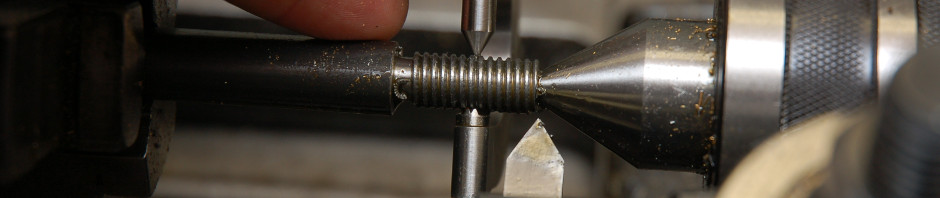
Finally, I needed to remove the axle so that the gear could be removed. This part was also a little tricky because the axle was stuck to the large gear pretty securely. The housing is closed on the back so there was no way to drive the axle out from that direction. So, somehow I needed to pull the axle out from the front. A slide hammer would work in this case but I don’t have one. It’s now on the list. I first wanted to break the axle free from the gear. To do this I used more PB Blaster and held the gear while using a wrench to turn the nut on the axle. I had previously run the nut up against the shoulder on the axle so that any tightening would turn the axle. I held the gear in place with the tip of a flat blade screwdriver pressing into the gear teeth. The screwdriver rested on the edge of the housing to lock the gear in place. Don’t do this with your good screwdrivers as it’s probably not good for them. Once the axle could be rotated, though not easily, with the gear locked I needed a way to “pull” on the axle. Shown in the picture below is the solution I came up with. I sandwiched a washer between two nuts on the axle so that as I rotated the wrench I could pull outward. After a few minutes the axle and gear were free.

Here are all the parts laid out after disassembly. Yeah, I forgot to take the wood off the handle in this pic but it’s already been done.

Next up, cleaning…but that’ll be in a future post.

What’s the yellow arrow in the 4th picture pointing at?
The grinding wheel axle. Edited post to include that.