Hendey Sector Gear Repair

My Hendey lathe has always had a good bit of gear noise when the powered feed is engaged. On the left end of the lathe, is a series of gears which connect the spindle to the quick change gear box. A while back, when I investigated the noise, I found that one gear was responsible for most of the noise. This gear is called the sector gear in the Hendey manual. I’ve highlighted this gear, technically two separate gears locked together, with a green arrow in the picture below. (This picture is from when I was cleaning up my lathe which is why parts are missing. I couldn’t get a good current picture as my lathe is up against a wall at this end.)

The sector gear is an assembly of two separate cast iron gears that sit on a brass hub. This assembly spins on a steel piece called the sector stud which is in the middle of the following picture.

I’d noticed that the gear ran loosely on the stud but wasn’t sure how to fix it back then. So, I left it alone, well maybe forgot about it, as it ran ok but was noisy.

Eventually, I decided to fix it. I took the gear off the stud and found there was about 0.015″ clearance between the two. The shaft is 11/16″ (0.6875″) and the brass part had worn away to a bit over 0.7″. I determined I’d need to bore the brass part out, press in a new piece, and bore that to 0.001″ over the diameter of the stud. I looked on McMaster and found that there were some oil embedded bronze sleeve bushings with an ID of 11/16″ and an OD of 13/16″. I decided that these would be much easier to use than the method I’d come up with previously. There wasn’t a bushing that was long enough to run the entire length of gear and I thought I could use two bushings end to end.

To start, I held the piece in the 4 jaw chuck, centered it, and proceeded to start boring.

To ensure that the bore was the desired size and had no taper, I picked up a used 13/16″ reamer.

The reamer performed well and I was able to press in the bronze bushings.

It was about this time that I started running into trouble. I removed the sector stud from the machine and found that my gear didn’t fully fit on it. I took more measurements and found that a bushing that I hadn’t pressed fit fine. I also discovered that the gear seemed to be hanging up where the two bushings were pressed together. I’d assumed that this wouldn’t be a problem but I guess tolerances stacked up against me. I mounted the sector stud between centers on my other lathe to lightly polish the stud as there were some ridges in it and I thought it might help. I found out pretty quickly that the stud didn’t run true at all. I wonder why….Oh…It’s cracked. Once I looked at it closely, I discovered there was a large crack which ran from the side of the wide flange to the base of one of the flattened sides (left of the flange in the picture).

I’m not sure where the crack or the wear on the brass hub came from. A lack of oiling could have caused the wear. It’s also possible that the bend could have caused the wear. The gears don’t look bad for being 100 years old and there’s no missing teeth though a few show heavy wear at the ends. Either way I’d need to make a new stud.

The flange on the stud is a bit under 1.5″ in diameter but the steel I had on hand was around 2″ in diameter. I started by whittling it down on the Hendey so I could move over to the Hardinge and hold the piece in a collet.

Once on the other lathe, I proceeded to remove a lot more material to reduce the diameter to 11/16″. I turned the end down to a little less that 0.5″ so I could thread it.

I then flipped the piece over and proceeded to turn the other side down to 13/16″ and finalize the thickness of the flange. Normally, you wouldn’t want to take a part out of the lathe and flip it around to work on the other side. Doing so can throw off the central axis of each portion and the angle between each portion might vary as well. I decided to make it this way since this part is fixed and doesn’t rotate. It also has a lot of adjustment where it fits on the machine. My collets also do a good job of holding pieces straight so I’m not concerned about angular misalignment.

The next step required going to the mill and cutting the slot shown in picture two. At this point I slightly changed the design. The part is oiled via the slot in the flange which allows oil to travel down into the horizontal portion of the slot. This slot is open on the end which does help oil the end of the brass part of the sector gear. I think it also allows the oil to just run through the part and drip out. Due to this, I didn’t run the slot all the way to the end on my part. I know it’s me versus the engineers at Hendey who made a part that still functioned after 100 years. So, I might be wrong. As a result, I’m going to keep an eye on it to see how it does. If I end up changing my mind I can always extend the slot to the end.

I supported the piece from both sides with a collet block and my angle plate. My slot is also a smidge wider since this was the closest cutter that I had.

Then I flipped it over to mill the flats onto the larger portion. Aligning the part was as little troublesome. Eventually, I placed a piece of 3/16″ square stock into the slot and indicated off of it.

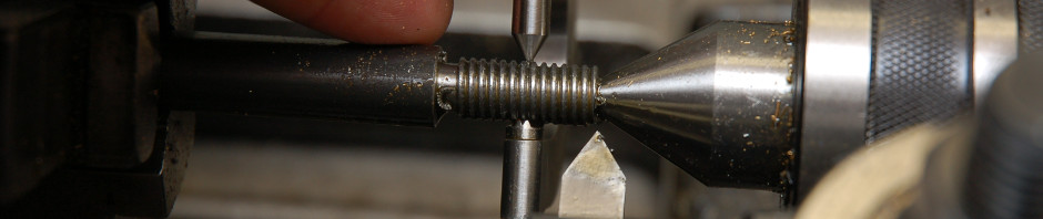
After the milling operations were completed, I placed the part back in the lathe and turned the end down so I could thread it also.

Below is a comparison of the old stud (on bottom) compared with my new one (on top). The old one had some numbers and letters stamped in it which I’d guess is a part number. I didn’t attempt to duplicate it though. I doubt the next guy would have any better luck ordering replacement parts than I did.

I ended up using an adjustable reamer to fix the issue I was having getting the gear on the stud. As expected, only a little bit of bushing material had to be removed to get a good fit. After that I put the parts back on the lathe and adjusted the clearance on the gears.

Once I turned the lathe on I engaged the feed and was rewarded with a quieter running lathe. It might also run a little smoother but I’ll have to use the lathe some more to find out. Another item marked off the list!

Posted in Metalworking, Projects, Repair | Tagged , , | Leave a comment

Hendey Lathe Replacement Part

I posted this before (I thought) but when I looked at it today, it was blank. So, I’ll try again…

When I got my lathe it was missing a piece which locks the cross slide to the taper attachment. It also covered the cross slide screw to keep chips out. The area in the middle of the picture is where it should be.

I came up with a simple design made out of aluminum to replace it. It won’t look the same as the stock one but should do the job adequately. I started by doing some milling on the pieces.

I got to use a new shell mill on the project and it made machine a large area much quicker and easier than running it over with a 0.5″ end mill.

I flipped the above piece over and milled out the area where the dove tail would go.

I placed the parts on the lathe to figure out how much I needed to shorten the top piece.

The top piece needs a couple of holes drilled in it for the bolts that attach it to the lower piece. It also needs a slot milled for the threaded post to pass through.

With that step complete, I used some home made transfer screws to mark where I needed to drill through the lower piece for the long bolts. Normally, you’d want the transfer screws to stick out less but these holes were pretty shallow.

Next, I proceded to drill and counterbore the holes for the long bolts.

I test fit everything again and then hit it with some black paint to match the rest of the lathe.

Since making the part a few weeks ago I found out the slot needed to be a little longer. A quick trip to the mill fixed that issue. Other than that it works out well functioning as a cover for the cross slide screw.

Posted in Metalworking | Tagged , , | Leave a comment

Gorton Rotary Table Clean Up

I picked up a 15″ Gorton rotary table recently. It had sat for a while unused. Due to this, it had developed some rust and would not easily move. A rotary table, as you might have guessed, is a tool with a flat top that rotates. While the table can freely move, it is much more useful to use a small hand wheel to accurately rotate the table. A scale, measured in degrees, is available around the circumference of the table to aid in positioning.

As opposed to describing the steps I used to clean it up I made a short time-lapse video instead.

Posted in Uncategorized | Tagged , | 2 Comments

Dividing Head: Use

In my last post I finished cleaning up my dividing head.  Now, I’m going to discuss using it.  A dividing head is a tool which divides a circle into equally sized portions.  If you want to turn a round piece into a hex shape you can use a dividing head.  A dividing head is also useful when making gears.  Gears are made by taking a round short cylinder and cutting out the spaces between the teeth. They also need equally spaced teeth to run smoothly.

Some dividing heads let you directly move the spindle in a process called “Direct Indexing”.  All dividing heads I’m aware of let you do “Simple (or Plain) Indexing” where plates with holes are used to increase the range of possible indexes.  My dividing head only does “Simple (or Plain) Indexing”.

The dividing head lets you divide a circle by placing a pin into holes on the index plate.  The index plate has a series of rings with different numbers of holes on it.  Some dividing heads have multiple index plates and some plates have different numbers of holes on each side of the plate.  The holes are there to provide a positive location for the index pin.  The pin is at the end of the crank arm.  When this arm is moved it turns a shaft that runs through the center of the index plate.  This shaft then goes through a reduction gear (usually a worm gear) and turns the spindle.   The chuck or collet holder is located on the spindle which holds your work. (Technically, it’s not the holes we care about.  It’s actually the spaces between the holes.  Holes work to count by though because each space ends in a hole.)

My dividing head has a 40:1 gear ratio between the shaft and the spindle.  So, 40 complete rotations of the crank arm results in one rotation of the spindle.  If you wanted to divide a circle into 4 pieces you’d need to do 10 compete turns of the crank arm between milling operations.  Simple enough but what if you wanted to do 23 divisions? Usually manufacturers would provide literature which included a table which tells what you need to do.  The table lists the number of divisions, number of index ring holes, number of full turns, and number of partial turns. Though there’s copies of this literature out there I couldn’t find one that had lines for every set of hole rings on my dividing head.

Here’s a pic of my dividing head in use on a project I haven’t posted about yet.  This is to say sorry because I’m sure you came to see cool pictures and instead you ended up with math.

To solve this problem I turned to math and wrote a script to create this table.  First, you need to know the worm gear ratio of your dividing head.  This is found easily enough by counting the number of full rotations of the crank arm to get one complete revolution of the spindle.  As mentioned earlier, my dividing head has a 40:1 ratio.  This seems to be a standard on dividing heads but check yours to be sure.

We know that for how many degrees the spindle rotates the crank arm will rotate 40 times as much.    The equation for crank rotations is:

crankdeg = 360/divs*wg      where

crankdeg is the angle the crank arm will move for each division

360 is the number of degrees in a circle

divs is the number of divisions of the circle you want

wg is the worm gear ratio

The number of full crank turns can be found by:

wholeturns = floor(crankdeg/360)

where floor is a function that rounds down the value inside to the nearest whole number

The number of partial turns is then:

partialturns = (crankdeg-wholeturns*360)/360*indexval       where

indexval is the number of holes in the index plate ring

For a given number of divisions (divs) you try different indexval values until partialturns is a whole number.

Example time.  Let’s say we want to get 23 divisions.

crankdeg = 360/divs*wg = 360/23*40 =  15.652*40 = 626.09 deg

This tells us the crank arm needs to move 626.09 degrees between every division.  Since this is over 360 deg and under 720 deg we’ll be cranking somewhere over 1.5 turns.  The number of whole turns can be found by:

wholeturns = floor(crankdeg/360) = floor(626.09/360) = floor(1.7391) = 1

The number of partial turns can be found by trying out different numbers of holes on the index plate.  My index plate has the following number of divisions: 66 62 58 54 49 47 46 43 42 41 39 38 37 34 30 28 24 18.   Lets try 34.

partialturns = (crankdeg-wholeturns*360)/360*indexval = (626.09 -1*360)/360*34 = 25.131

Unfortunately, 25.131 is not a whole number so this is not an acceptable index val.  Now lets try 46.

partialturns = (crankdeg-wholeturns*360)/360*indexval = (626.09 -1*360)/360*46 = 34

Yay!  34 is a whole number.  So, we find that, using the the index ring with 46 holes on it, we need to turn 1 whole turn and then place the index pin in the 34th hole from where the index pin currently is. Don’t count the hole the pin is currently in.

We can check our answer using the following process.  Since we want 23 divisions of a circle the spindle needs to turn 360/23 = 15.652 degrees.  The crank arm is going to turn (1+34/46)*360 = 626.09 deg.  When we account for the worm gear reduction we get 626.09/40 = 15.652 deg.    Since the answers match this result checks out.

I want to point out that partialturns really needs to be a whole number.  Something like 34.05 is not good enough.  Why?  We can use the math about to show why.  In the example above we found the crank turns 626.09 deg.  If we hadtried an index val of 54 we would have ended up with partialturns = 39.914.  Say we decided to make that 40.  We’d get (1+40/54)*360 = 626.67 deg.  The spindle would rotate 626.67/40 = 15.667 deg.  After 23 dividions the spindle would have rotated 23*15.662 = 360.34 deg.  That additional 0.34 deg is probably going to cause you problems.

To create a new table for a dividing head we need to evaluate a range of divisions.  For each division we would try each indexval until partialturns is equal to a whole number.  For some divisions there may be multiple indexvals which are good.  For other divisions there are no good answers.

Running my script, I found that my dividing head can have 206 different settings between 1 and 2640 divisions.

If you have Octave or MatLab this script should work for you.  Sorry, it won’t let me indent it here.

#Calculate table for Dividing Head

wg=40; %Worm gear reduction
indexvals=[66 62 58 54 49 47 46 43 42 41 39 38 37 34 30 28 24 18]; %Available index plate values

divrange=1:4000; %Number of divisions
count=1;
for i=1:length(divrange)
for j=1:length(indexvals)
crankdeg=360*wg/divrange(i); %Total deg that needs to be covered
wholeturns=floor(crankdeg/360); %Whole turns on the index plate
partialturns=(crankdeg-wholeturns*360)/360*indexvals(j); %Partial turns on the index plate
if abs(round(partialturns)-partialturns)<1e-10 %Deal with roundoff error. If partial     turns is an integer…
table(count,:)=[divrange(i) indexvals(j) wholeturns round(partialturns)];
count=count+1;
end
endfor
endfor

This script will create a variable called table which is a matrix with four columns.  The columns are, from left to right: number of divisions, indexval, whole turns, and partial turns.

If you can program I’m sure you can adapt it to your language.


Sometimes you might want to rotate a part by a specific number of degrees.  This is called “Angular Indexing”.  To do this, the above math can be used with a specific value of divrange.  This is found by:

divrange = 360/desireddeg     where

desireddeg is the number of degrees to turn

For example, if we wished to turn 35 deg then

divrange = 360/35 = 10.286

crankdeg = 360/divrange*wg = 360/10.286*40 = 1400 deg

wholeturns = floor(crankdeg/360) = floor(1400/360) = 3

partialturns = (crankdeg-wholeturns*360)/360*indexval = (1400-3*360)/360*18= 16

To turn 35 deg we’d need to turn 3 whole turns and rotate 16 holes on the 18-hole ring.

The is a slightly easier way to determine this as well.  With our 40:1 gear ratio we know that each turn of the crank arm will turn the spindle 360/40 = 9 deg.  To turn the spindle 35 deg we’ll need to turn the crank arm 35/9 = 3-8/9 times.  Since we don’t have an 8-hole ring we’ll need to convert the denominator (9) in 8/9 to something we do have.   18=9*2 so we can expand the fraction 8/9 to 16/18.  We’ll need to turn the crank arm 3 and 16/18 turns which is the same result as we got above.

Posted in Metalworking | Tagged | Leave a comment

Dividing Head Refurb: Part 2

In Part 1 I went over disassembling this dividing head.  Now it’s time to put it back together and make some of the pieces that were missing.

I started by giving everything a good washing and left the parts to dry in the Florida sun. So, 2 minutes later they were dry.

I cleaned all of the threaded holes with the thread chasing tap.  Some of the holes were so messed up I had to clean them up with a thread cutting tap.It turned out that a woodworking clamp worked well to slightly spread the sides so I could get the core of the dividing head back in. One of the screws was missing but I made another on the lathe.  I’ve shown making screws before so I’ll skip rehashing that again.  The new screw is on the left.

I also went through the chuck.  It’s a design I haven’t come across before and I have to say I’m not a big fan.  The jaws move on normal threads as opposed to a scroll.  Unfortunately, they are open to the environment which collects chips.  It’s recommended to use oil on these type chucks from what I’ve read.  Grease will hold chips inside the chuck which is undesirable.

I reassembled everything and put some black paint on some parts of it.  At this point I’m back to where I started.

I’m missing several parts from the dividing head which I need to make before it can be used.  I need to make the plunger assembly and the arm that holds it.  I also need to make another sector arm and the ring that holds it.

I decided to make the missing parts primarily out of aluminum.  I have a bunch of aluminum drops and it’s much easier to machine.  I also used the Hardinge which left me with a great finish.  The picture below shows test fitting the plunger assembly temporarily with a bolt. Next, I turned the knob for the plunger assembly and am about to part it off.I decided to press fit the plunger body into the crank arm.  To do that I bored a hole 0.001″ smaller than the diameter of the matching surface on the plunger assembly body.  

Next, I drilled holes at the ends of the slot and milled out the inside.Here’s all of the parts of the crank assembly and arm.  The plunger is spring loaded to press the tip (top right) into the holes of the index plate.  The knob (center top) has a small pin in it that allows the plunger tip to be held out of the plate holes.  The next part I worked on was the missing sector arm and the ring that holds it.  I started making the ring by cutting a section of 1/4″ plate out and mounting it on an arbor.  I turned the outside diameter down to the appropriate diameter and trimmed the thickness down some.  I then removed the ring from the arbor, chucked it, and bored it. I decided to make the sector arm look Z shaped with one long leg.  To help make the arm perpendicular to the ring, I turned the inside vertical surface to a be a smaller diameter than the ring diameter.  This results in the arm having two points of contract with the side of the ring.The following picture shows how the ring sits on the currently existing arm.  Part of me wanted to make these pieces out of brass to match the existing arm but I didn’t have any brass sitting around.  Here’s I’m marking the ring to tap some #4 screw holes to connect the two pieces.With all the pieces finished I was able to put everything together.  The plunger body pressed into the arm easily using the arbor press.   With that finished I’m done fixing up the dividing head.  In the next post I’m going to discuss how the dividing head is used and the math behind its operation.

Posted in Metalworking, Projects | 1 Comment

Dividing Head Refurb: Part 1

A little over 2 years ago I purchased this dividing head from an OWWM member. He said it was missing a few pieces and jammed up but the price was good. Finally, I’ve gotten around to working on it. The dividing head has no brand on it but there is a patent stamped into the head. According to the patent records online (from 1890!), this dividing head was made by Cincinnati. While going through the dividing head, I found 47X stamped into multiple pieces. The patents indicate this dividing head was used on a horizontal milling machine. It has a “drive shaft” allowing it to be driven by the milling machine.

If you’re not familiar with a dividing head, it’s a device for dividing a circle into numerous pieces.  It does this precisely by gear reduction and an index plate.  This one can do between 2 and 2640 divisions of a circle but probably not every integer in that range.  More on this in a future post.

This is what I started with. There’s a three jaw chuck, large locking “nut”, curved cover in the box, and bag of small parts.

First, I took the index plate off which just slips off the housing.

With the plate out the screws can be removed that hold the “drive shaft” housing. The wood dowel helped me to move the spindle block without damaging anything. The dividing head has two bolts with a T shaped head to lock the spindle block in position. They can be removed by orienting the hole in the spindle block to remove them. To remove the spindle first required removing the worm gear. The first step in this is to remove the brass “nut” on the worm gear shaft. It wasn’t tight and I found the best tool I had to remove it was a pair of bent needle nose pliers. Once the “nut” was removed, a spacer, and the part I’m going to call a thrust bushing can be removed. The bushing just sits on the shaft but it took be a little bit to figure out a way to grip it to pull it out using some large retaining ring pliers (not the adjustable wrench in the pic).

At this point I had access to the worm gear and the shaft it is on. This took me the longest time to get out. Eventually, I realized I could thread a regular hex nut on the end of the shaft that I could pull on with my fingers. While doing this, I turned the spindle (using the gear and shaft that the arm with plunger would normally turn) so that the force on the worm gear would help push it out. Finally, it came out. There are some spacers that go on the smaller end of the spindle. I thought they were threaded in initially but it turned out they just slip over the spindle. I oiled them and was able to get them removed with a magnet. There’s also a big round piece that screws in to hold the spindle in place. It was already removed when I got the dividing head but, for anyone else, it has to be removed to get to the spacers. This circular piece holds in a couple parts that lock the spindle in place. The piece was held in place by a pin on the back side of it. To remove it, I slowly worked it loose going around the outside with some scrapers. With the worm gear removed, the spindle is able to be removed in the direction of the smaller end. In the picture, the spindle brake piece is shown on top of the spindle. 

To get the shaft out this casting I needed to first remove the bevel gear which required moving a taper pin.  This pin was stuck in and I tried driving it out with a hammer.  I was afraid I might damage the casting if I kept it up and instead chose to drill it out.

At this point I had the diving head completely disassembled.I’ll cover reassembly and making some missing parts in future posts.


Posted in Metalworking, Projects, Repair | 2 Comments

At Home Rust Bluing

The other day I decided to improve the hold downs on my milling vise. My current hold downs use a stack different sized washers that were with the mill when I got it. I decided to turn some pieces out of steel to replace the stack of washers. My “new washers” are 1/4″ thick and around 2″ in diameter with a 3/8″ hole.

I turned two of them and then decided to “cold blue” them with Birchwood-Casey Perma Blue. A simple dunk of the part in the solution resulted in a nice uniform deep blue color. I liked the results but the I’ve read this coating is very thin. The solution is also relatively expensive for the amount you get.

Due to this, I started looking into other types of coatings to use. I ended up running across a YouTube video discussing a type of bluing that can easily be done at home. I followed the instructions in the video but didn’t get as good of results as I hoped. Instead of the desired uniform blue coating I ended up with a mostly blue coating speckled with spots. He didn’t in the video though. This lead me to do more research on the method. It turns out the video is describing a variant of a technique typically used by gunsmiths to blue firearms. I was then able to read up on the technique and try it out.

The technique consists of lightly rusting the piece of steel and then boiling it in water. Boiling the piece in water converts the typical red rust into a black oxide (also called magnetite). Unlike red rust, which will slowly eat up the steel, this black oxide coating is stable and when oiled provides a durable coating.

I took my washers with the speckled finish and stripped it off using some vinegar. Next, I used some 220 grit sand paper to smooth out the surfaces. Below is one of the washers I started out with.

Before starting, I thoroughly cleaned the piece several times with Acetone. I also wore latex gloves the entire time to keep from contaminating the part. Originally, I cleaned the washer with mineral spirits but people online indicated that mineral spirits can leave a residue. It’s important to completely clean the part to remove any oil and keep it oil free throughout the process. As you might guess, oil will stop the formation of rust. To speed up the rusting process, the video uses mixture of hydrogen peroxide and table salt which is brushed onto the washer. The reaction fizzes white and then turns rust colored.

As suggested by the video, I used a heat gun to dry the washer off which quickly resulted in a light rust coating. I repeated brushing on the solution and drying it to build up a uniform coating of rust. If the heat is carefully applied, the solution will dry after a few seconds which keeps the solution from building up along the edges of the washer. The build up can in the rust not looking uniform.

After uniformly rusting the piece, it is then placed into boiling distilled water. Some use tap water but others suggested distilled. The piece is kept in the boiling water for around 5 minutes. From what I read, it’s the heating of the rust in a low oxygen environment which results in the conversion to black oxide.

After the piece is removed, it is coated with a relatively thick layer of magnetite which is loosely attached. On the threads I found, the gunsmiths referred to this a “velvet” which is a pretty good description. As you can see in the picture below, the surface is a matte black and you can still see the brush strokes (and a damp spot). Once removed from the boiling water the piece will dry quickly but should be moved around to keep the water from pooling in one spot which will effect the finish.

The gunsmiths then say to remove the “velvet” by either gently wire wheeling or using de-oiled steel wool (I sprayed mine with brake cleaner) to clean the surface in a process called “carding”. The video I linked to doesn’t mention this step. The first time I went through the process I didn’t “card” the surface which I think is what caused the initial poor results I ended up with. After “carding” the surface it has a shinier uneven look to it. The picture below shows the carded surface though I did still need to clean it a little more.

At this point, the process is repeated . The piece(s) are then re-rusted.

Then it’s back into the boiling water.

The picture below shows the washer partially carded on the bottom with the top still the in velvet state though I’m not sure it comes through well.

I repeated the process five times to build up and even out the coating before moving on to the final step of boiling the piece for an additional 20 minutes after carding. This last step is important and seems to be done to make sure all of the red rust is converted. After that, the washer is allowed to dry before being submerged in oil. I left the washer in the oil for a while to make sure it received a good coating. The addition of the oil results in the color of the surface changing to be a dark blue which is where the name bluing comes from.

Below shows a picture of the washer I cold blued on the right and the one blued using the method I described here on the left. The cold blued one looks a little rougher because I didn’t sand it prior to coating it.

I ended up using the two washers above on my vise to see how the coatings wear. Overall, I’d say I have one of the best looking hold down washers around.

Obviously, this fancy of a finish is overkill on a part like this. But, I wanted to perfect the process and I’m very happy with the quality I ended up with. I’d even say it would look good on a firearm. The process described above takes about an hour so it’s probably best to wait and do multiple pieces at once. The process is also non toxic as it doesn’t use any acids which are sometime used in bluing. About the only concern is the boiling water and the hot part that you remove from it.

I also found out that if you heat the hydrogen peroxide and salt solution will become more active. If you dip your part into the hot solution it will aggressively pit it which is not desirable. The hot solution will also have deleterious effects on stainless steel cookware. If a stainless pot is used for the boiling water the part it will show some stains after use but they can be removed by scrubbing. Either way I suggest a plastic container for the hydrogen peroxide solution and using cheap pots to boil the parts.

All in all, this would make a pretty good at home science project with the adult doing the boiling part. You could buy some standard big Zinc coated steel washers from the store and remove the Zinc coating by soaking in vinegar. The washer could then be cleaned with acetone, lighter fluid, or soap and water. You can rust it using the hydrogen peroxide and salt solution and let it dry without the aid of heat. Alternatively, you could warm it in the oven to dry it more quickly. Boil the washer as described and then let it cool down before carding. A green Brillo pad should work well. You probably won’t get a perfect finish but you can see the process.

In my reading I found that gunsmiths of old would use rainwater to boil the firearms in which was probably cleaner than the other options. These days at-home and professional gunsmiths use special mixtures which are commercially sold to coat the surface that promote rust. The part is then placed in a humidity box which results in uniform rust. The rest of the process they use is pretty similar to what I described above.

Most modern firearms though are hot blued using a process that has acids at around 300 deg which doesn’t sound like something I’d want to do at home. Of course, if you’ve followed this blog for a while, you know I would try it if I felt the need because it can’t be that dangerous. Right?

For more reading see the Rust Bluing section of a Wikipedia entry.

Posted in At home science, Metalworking | Tagged , | 1 Comment

Wood Canoe Build: Part 3

In Part 2 the canoe was nearing completion.  In this post I’ll discuss finishing it.  The next step was to put a small keel on.  The keel was constructed by trimming a piece of wood to the profile of the bottom of the boat.  The instructions listed a series of points which I splined with an aluminum ruler.

The keel was attached using stainless steel screws from the inside of the canoe and epoxy.  I also utilized this fancy clamping system while the epoxy was drying.

The ends of the keel were sawed to rough shape after marking a line with a compass.The ends were sanded to final shape and I caulked the seam between the keel and hull.

The next step was to install a central brace.  The instructions again detailed how to trim the ends to aide in fitment of the brace.  

Once the brace was installed, using stainless screws through the side of the hull, the rigidity of the canoe was remarkably increased.  Before the brace, the canoe could be twisted along the length without much effort.

The last step in the assembly of the canoe was to install supports for seats.  I marked out the side supports and cut them out.

The side of the ship is curved and required sanding of the support to properly fit it.  Once it fit well, it too was attached with stainless screws and epoxy.

The cross braces were the next part to be installed.  They were sanded to fit an screwed into place.  Supports for seats were installed in the bow and stern of the canoe but in different positions.  At this point I still needed to work out actual seats but that will be covered below.  

Now it’s time for the most exciting part…painting and painting and more painting.  I decided on a navy blue for the hull, a tan color for the inside, and white for the other parts.  Below you can see the progress on painting the bottom.

This shot shows the canoe as I was painting the inside.

Once I was done with painting, I decided on a simple setup for the seats.  They were composed of 1/4″ plywood with some cut down foam.  

Here’s a few shots of the canoe while it was sitting out to have the paint harden in the sun. I haven’t tried it out yet due to all the Covid-19 issues but I will at some point.  When I do, I’ll update the post.


Posted in Projects, Woodworking | Tagged | 3 Comments

Wood Canoe Build: Part 2

The work on the canoe continues from Part 1.  Once the sides and bottom had finished drying, it was time to make the pieces start to look like a boat.  The instructions detail how to assemble the hull using a simpler version of a method called “stitch and glue.”  The traditional “stitch and glue” uses wire to attach the pieces of the hull together similar to how fabric is sewn together.  This version uses duct tape instead of wire which turned out to be good and bad.

The first step was to tape the ends together and place temporary spreaders near the top of the sides.  This resulted in the ends pulling apart due to the crummy duct tape I started with.  To overcome this, I drilled small holes near the edges of the ends and used wire to hold the ends together.

Next, I flipped the boat over and started working to attach the bottom to the sides.

I had some doubts about the duct tape successfully holding everything together after the previous experience.  This time I used small tacks to assist the duct tape.  I drilled angled holes first to keep from splitting the plywood.  Then I tapped in the nails and set them below the surface.I also upgraded the duct tape to a heavy duty version which was thicker and had much better adhesive. To apply the tape I started in the middle on both sides and alternately worked my way to the ends as instructed.  After a lot of taping I finally had something resembling a canoe. To permanently hold the boat together I used epoxy and fiberglass tape.  Alternately, the instruction manual says an epoxy fillet can be used on the inside seams.  In retrospect I think it would have been simpler to use the fillet but I managed with the tape.The ends of the boat don’t come nicely since its two pieces of 1/4″ plywood.  The instructions recommend rounding it over with thickened epoxy but I didn’t like that idea.  Instead I epoxied a piece of wood in place and shaped it appropriately.

At this point I was able to start working on the outside of the seams.  Again, I used fiberglass tape and epoxy.  I rounded the edges to help the fiberglass tape stay flush to the surface around the edges.  Eventually, I found wetting out the tape and boat with epoxy helped keep the tape in place. The next step was to start working on wood strips that strengthen the top edges of the boat.  These strips, known as the gunwales and inwales, had to be built up from shorter lengths of wood to reach the required length of 16 ft.  The instructions recommended a simple scarf joint which is a much stronger joint than if the pieces had been butted together.  The scarf joint tapers the wood on both sides of the joint.  To form each joint, I sawed off the waste, stacked both pieces together with the top one offset, and planed both pieces together to leave a smooth surface with a consistent angle.The two pieces were then flipped over, overlapped, and glued together.   The pieces were clamped together and allowed to sit until the glue was dry.  Attaching the gunwales (the piece on the outside) was done first.  It required a bit of glue and a whole lot of clamps.  The instructions mentioned making the gunwales flush in the middle and then raising the strips slightly toward the ends.  The excess material is planned off later.  This is said to give the canoe a “lighter” appearance.  The instructions didn’t detail how to bring the two gunwales together.  Looking for pictures online showed that some builders choose to cut the two pieces off with end of the boat.  I wanted to bring the two pieces together more gracefully.  To do this, I first glued one gunwale in place and trimmed the edge to be parallel with the central axis of the boat.  The other gunwale was then clamped into place and trimmed to fit with the first gunwale.  Once happy with the joint, the second gunwale was glued in place.

The inwales were then clamped and glued into place.  The instructions call for triangular pieces to be glued on the ends of the canoe which go over the ends of the inwales, hull, and gunwales.  I didn’t like the way that would look and instead decided to inset the triangular pieces to be fush with the hull.  This required removing some of the thickness from the inwales at the ends of the canoe.

At this point the project looks a lot more like a canoe but there’s still more work to be done.  That will have to wait until Part 3 though.


Posted in Woodworking | Tagged , | 1 Comment

Wood Canoe Build: Part 1

Over winter I’ve been building a wooden canoe.  Specifically, I’m building a Quick Canoe designed by Michael Storer.  Tragically, it’s in metric so who knows if it’ll come out to be the right size.  It’s a two seat version that is a little under 16 ft long.  The plans call for 1/4″ plywood and I’m using exterior grade as opposed to marine grade plywood due to price.

The hull is made up of six plywood panels.  Specifically, there are front and back (sorry…bow and stern) panels for both sides and the bottom.  The plans detail the positions of points which are lofted to give the final curve.  I started by cutting out the two pieces for the bottom.  To do this I marked out the center line and measured out from it for each point along the edge.  I lofted the curve by holding a thin piece of wood against small nails I’d hammered in at each point and marked the curve with a pencil.

After lofting the first piece, I cut it out with a jig saw and then sanded the edges to the lines I’d marked out.  With this piece at the final shape I could use it as a large template.  I traced its edge onto the second piece of plywood and once again cut it out with the jigsaw.  Next, I clamped the two pieces together and used a top-bearing flush trim router bit to bring the second panel to the required shape.

Here’s a close up picture of the router bit. Now I have two very floppy and warped bottom pieces.I used the same process for the four side pieces.   This time using the first side piece allowed me to save marking out the other three panels.The side panels are marked out from a datum line which is the right edge of the plywood piece shown below.

Here’s all four side pieces.The instructions call for backer pieces of plywood to be used to join the front and back plywood panels together.  These were easily cut out on the tablesaw.  The backer pieces were coated with strengthened epoxy (two part epoxy with West Systems 404 High Density Adhesive Filler) and held in place on larger panels.  Below shows the bottom panels getting epoxied together.Unfortunately, I had a lot of squeeze out I was unable to remove it before it dried.  At least I know it’s not a dry joint.  I started to remove some of the squeeze out after it had dried but decided it wasn’t worth the effort.The side panels were easier to glue up and I made a better effort to remove the squeeze out.At this point I have three very cumbersome pieces of floppy plywood that will hopefully become a boat.

Posted in Projects, Woodworking | Tagged , , | Leave a comment