After painting all of the parts it is time for reassembly. The first thing I did was tap the holes for small #3 screws to hold hold the badges on. I used my small drill press to hold the tap vertical while I turned it by hand.

Here is the reassembled motor which I had to disassemble later.

Heres a pic of the major components back together again.

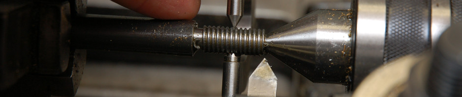
This is the front pulley assembly pressed back together with my small arbor press.

Here is that assembly in place in the head casting. To adjust the speed the fork moves the bottom half of the pulley up and down changing where the belt contacts the pulley.

The speed adjustment, quill feed handle, quill spring, and other small parts have been put back on the drill press.

To fix the shaft with the broken key way, A_PMech off of GarageJournal.com milled a new key way on the opposite side of the shaft. He also bored a plastic bushing in the rear top pulley half and turned the shaft down to match it. He put a very nice polish on it to make speed adjustments smooth.

To get the shaft on the motor I had to remove the rotor, hammer the shaft down until it’d fit in my press, and then press it into position.

I finally got the shaft in place and mounted the motor onto the drill press. After that I was able to install the top rear pulley half and the belt. At this point I was able to operate the drill press though not to drill!

I was unable to find a machine shop to repair my original spindle but was able to locate as used one in good condition on Ebay. It came with a quill, bearings, and a chuck as well.

With the spindle in place I once again had a working drill press!!

One important specification on a drill press is the TIR or Total Indicated Runout. A theoretical drill press rotates the drill bit perfectly along it’s axis and results in a hole exactly the same diameter as the drill bit. In reality there is some wobble in the drill bit. To measure this wobble a dial indicator and a precision milled piece of drill rod is used. The spindle is spun by hand and the TIR is read off of the dial indicator. The TIR is the remainder after subtracting the lowest dial indicator reading from the highest. When I reassembled my press I got about 0.005″ TIR which I thought was good. A member from another forum reccomended I check this again as that number was high for a machine of this quality. When I did I got even higher numbers in the range of 0.015″ to 0.020″ TIR. I measured the runout on the spindle taper of around 0.0005″ which lead me to believe my chuck was bad. It turns out I had some lucky misalignment to get the 0.005″ TIR from before.

To remedy this, I picked up a nice German made Rohm keyed chuck. After installing it I got a reading of less than 0.001″ TIR one inch down from the chuck and 0.002″ at the bottom of my drill rod. Much much better!

Here is the press with the new chuck installed. I also picked up some plastic knobs to put on the quill feed handles. The knobs are a small detail but make using the drill press much better.

To finish my drill press off I wanted to be able to reverse the direction of the motor to use left handed drill bits. Left handed drill bits are useful when trying to remove broken bolts which I’ve had to do before. To do this I used a type of switch called a drum switch. This drum switch has 6 terminals and the order than they’re all connected depends on the potion of the switch. Here is a pic of it wired up for testing. I mounted it on a piece of angle iron held on by the two left motor bolts.

Here it is all buttoned up and read to go.

Here are some pics of it finished.


It works extremely well and I’m very happy with how the restoration turned out. I plan on having this drill press around for a very long time!
If some reader has happened upon my blog and is curious about how to wire their Clausing drill press with a drum switch here is a chart I made up. If your numbers don’t exactly match mine you can sort out which wires are for the running and start windings. If your drum switch internal connections are different though you might want to find another diagram. Triple check your connections so you don’t fry your motor. This should probably work for any similar wired motor and drum switch as well. Either way don’t blame me if this fries your motor!

Be sure to check out my other posts on restoring the Clausing drill press! Ups and Downs Small Parts Stripping and Painting

Ummm…you appear to have forgotten to mention your lovely assistant who put her tiny hand inside your drill press to help reattach a few pieces…. 😉 Great job otherwise, dear!
Great job on the drill press. I just picked up a very similar model in good mechanical condition at an auction for $100.00, but it have been painted a hideous green. I wasn’t sure if I was going to redo mine, but after seeing your beauty, I’m leaning that way. Mine has identical head castings and base, but my table is quite a bit larger and heavier. I just added a jack system to it for lifting and lowering it. My motor isn’t original and is a single speed, which only lets me go down to 800 rpm. I’m thinking of going with a 3-phase motor and VFD to get me in the speeds I need.
Also, at the same auction, I picked up a Rockwell 46-499 for just $25.00! It looks great and only needs a front door and a hand wheel.
Jack
I just picked up one yesterday from an estate. Been neglected like yours… Even has the arc of shame on the table. The rats that built a nest in the top were the worst so far.
Thanks for the step by step. I’ll be following this as a HOW TO manual. Excellent work!
Congrats! They’re a great drill press. Let me know if you have any questions.
I printed out your pictures and notes. It has been very helpful. measured the bearings, found the 2 small ones are 6205-2Z (2RS) and the big one is a 6007-2Z (2RS) I bumped into some issues, mostly sticky gunk and solidified grease. I cleaned up the column, foot and table, working on the head right now.
I’ll let you know if I get stymied. Thanks again for the blow by blow! This really rocks!
Someone prodded me into posting about my resto. I really appreciate your effort at documenting what you did. Made my life very easy….
https://budgetmachining.blogspot.com/2018/11/phil-over-at-busted-nuckles-recently.html
I’m happy I was able to help. Congrats on your restoration too. It looks like it came out great!
David, outstanding restoration. Very impressive. Great articles.
Can you tell me the best route for removing the tension spring on the motor pulley. Just bought a 15 inch and the sheeve is bad as well as the key. Thanks.
If I remember correctly, the cap on the pulley assembly is held on by a circlip in the middle of it. To get it off you need to press the cap down and remove the clip. After that it should come apart. At the time I think I drilled a hole in a piece of wood that was a little larger than the clip. I placed it onto the cap and used some wood working clamps to compress the spring.