On my last post I mentioned that one of the things needed to receive broadcast TV is an antenna. While you can buy an antenna, you can also build one that can be optimized for the signals you want to receive. So, what kinda of antenna do you want? There are several questions that need to be answered before you pick an antenna. The first being what frequencies do you want to receive? If you look at the top chart from my previous post, you’ll see that most all the channels are in the UHF range but there is one, 10-1 WALA, that is in the VHF-HI range. So, I’ll need an antenna that is good at picking up VHF-HI and UHF frequencies. The next questions have to do with size and location? If you’re willing to put an antenna outside or in your attic the reception will be much better. You can use a larger antenna in these locations. Experimentation with the antenna I made two years ago showed that an antenna outside did better for me than one in the attic or on top of my TV. Since I want an outside antenna size isn’t an issue for me. I started looking around for an antenna that met these criteria two years ago before the switchover to digital and found the “4 Bay Bowtie Whisker” antenna from this site. DIY TV Antennas
The site has a lot of technical information with and field test comparisons of different types of antennas. The comparisons are between variations on the Bowtie whisker antenna, another DIY design called the Gray-Hoverman, and some commercial offerings. If you take a look at this page you can see the results. To sum it up the Bowtie antennas have good reception, better than the commercial offerings in some cases, over VHF-HI and UHF frequencies. The basic Gray-Hoverman design tested has strong UHF reception but is weaker than the bowtie in the VHF-HI range. There is a modification to the Gray-Hoverman antenna that is supposed to make it perform better in the VHF-HI range but I haven’t pursued it. I might in the future.
If you head over to the drawings page you can find some nice pdfs to help you build the Bowtie antenna of your choice. There are several variations on the antenna on this page that change the size of the whiskers. If you check out the FAQ page you can find recommendations on which length whiskers to pick based on the channels you want to receive. In my case, I chose the 9.5″ whiskers because I need to pick up WALA which is real channel 9. Please go and check out the site for sizing and details on the antenna.
So, two years ago I built a 4 bay Bowtie antenna using what I could find locally. I ended up using steel wire to make the antenna which, as I knew it would, has rusted overtime. The wood I used was also untreated so it has begun to rot. It has done a good job for two years but it is beginning to look a little sad and the performance is dropping. What does my antenna look like now?

Yeah, not to good. Fear not though, because I have rebuilt it! I reused much of the old antenna, specifically the reflector and central mast, because it was still in good shape. I ordered some 1/8″ aluminum wire from McMaster-Carr and decided to get rid of the wood and as much metal as possible. The metal rusts and probably minutely affects the reception of the antenna. Previously, wood was used for the “standoffs” that held the wires to the central mast. This time I decided to use PVC pipe in place of the wood and nylon bolts. In the picture below, the PVC standoffs are already attached and I’ve circled one in green. The wire screen on the back (bottom in this picture) of the antenna is called the reflector. As you have probably guessed from the name, it reflects the signal that hits it and serves two purposes. From the front, it bounces the signal to the whisker elements which are what actually picks up the signal. It also blocks signals coming from the back of the antenna which reduces interference. Reflectors can come in many different shapes and don’t always have to be a wire screen. The mast and reflector support are made of 1″ PVC. The PVC that supports the reflector was heated with a torch and then clamped into a wooden form to shape it. After the PVC cools it holds the new shape.

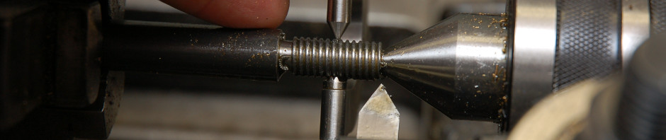
Let’s make some standoffs. The first thing to do is drill out a section of the PVC so that it will rest on the mast. To do this, I used a 7/8″ Forstner Bit which will remove cylindrical section of the pipe.

Next, the piece is cut down to length and three holes are drilled on the opposite side of the PVC. The center hole is drilled 1/4″ and the two outside holes are drilled to 0.21″. The center hole allows a bolt to pass through the standoff to attach it to the mast. The outer two holes are tapped with a 1/4″-20 tap for the nylon bolts which hold the whiskers in place. Note: Vise is useful!

There are two lengths of wire, called the phase lines, that attach the standoffs. So they don’t slide around, I filed two groves into the standoffs next to the threaded holes to hold the wire.

Once five standoffs have been made, I turned my attention to the whiskers. The Aluminum wire comes on a roll and when to cut a piece off it’s not exactly straight… Note: Vise is useful!

While you could pound on it with a hammer, there is a much easier way to straighten the wire. Clamp one end of the wire in your vise and the other end in a drill. Run the drill at a low speed while lightly pulling on the wire. After a few seconds you’ll have a nice straight wire! The longer you run the drill the straighter the wire will get. At some point though it’ll probably break so don’t go overboard.

The design calls for eight bowties that are 9.5″ on each leg and about 5″ wide at the end. The best way to make multiples of any object is with a jig. In the picture below you can see the simple jig I made for making the bowties and the straightened wire segments.

The steel bolt allows me to form the wire tightly around it and the nails at the end help shape the width of the bowties. Once they’re shaped I mark and cut them to width.

After a short time there are eight bowties. They don’t have to all be identical now because you tweak them once they’re on the antenna.

With all the parts made assembly is pretty easy. First, all the standoffs are attached to the mast with nylon bolts. Then starting at one end, you place the phase line in the grooves and then bolt a whisker on top of it. Note that the phase lines cross, but don’t touch, between the first and second and third and fourth standoffs. Once it’s all bolted together tweak the bowties to the correct size and bend them out a little bit to match the reflector angle. The center standoff doesn’t have whiskers that attach to it. It is known as the feed point because this is where you attach the coaxial to the antenna. To do this you use a device called a balun which matches the impedance of the coaxial cable to the antenna.
With the antenna complete, it is time to attach it to my high dollar mobile antenna test device. Yes, it is a ladder and a clamp. The reflector is about 36″ wide and 40″ tall. Obviously you wouldn’t want this on top of your TV. Alright, so actually I did two years ago for testing purposes. Outside vs inside does make a difference. (Be sure to follow the warning sticker on the ladder on don’t try to surf upwards on it!)

So, remember that other DIY antenna called the Gray-Hoverman? It turns out it is a very simple antenna to build so I gave it a try a while back. Plans are here: Hoverman HDTV Antenna. The site has a lot of technical info, comparisons, and design variations just like the other site. To make this antenna I rigged up another jig and bent the two pieces of wire that this design calls for. This antenna is still in good shape even though it’s made with steel wire because it has been kept in storage inside in the attic. It is still a large antenna (30 ” tall), but if you want a good antenna that is very simple to build this is it. The designs on the page call for a reflector as well, but as with the Bowtie antenna it is not a necessity but does boost performance. In a minute I’ll compare the results of these two antennas but first an important point or two.

Antennas work because they collect or emit electromagnetic waves. Aside from frequency, directionality and gain are two other features of an antenna that are important. Gain refers to the ability of the antenna to amplify the signal it receives. Directionality refers to the shape of the reception pattern of the antenna. Gain is usually measured in decibels and directionality is displayed in 2D or 3D plots.
A simple whip antenna like a regular car radio antenna has an omni-direction (spherical) reception pattern meaning it will increase the strength of the signal equally regardless of what direction the signal comes from. The whip antenna has a gain of 5.19 dBi. The dBi is a special unit that compares gain to a hypothetical ideal omni-directional radiator. Without a reflector the 4 bay bowtire antenna has a radiation pattern that looks like a figure 8 and a max gain of about 12 dBi at 686 Mhz. With the reflector, the gain for the front of the antenna increases to about 14.5 dBi and the back decreases to about 4 dBi at 686 Mhz according to plots from the site linked earlier. So, it’s still kinda of a figure 8 but one lobe is smaller. The Gary-Hoverman design has similar gains in the UHF frequencies but less in the VHF-HI range. Because of their non-spherical reception pattern the Bowtie and Gray-Hoverman antennas are called directional meaning they must be aimed in the direction of the signal.
Here’s a little not to scale drawing of the reception pattern (black lobes) of my antenna (red object) with the reflector looking down from above. At the center is zero gain and as you get further out the gain is stronger. So the farther away the black line is from the center the stronger the gain is in this direction. The elements are ahead of the reflector and this side of the antenna is called the front (up in my drawing). Perpendicular to the elements is the direction of strongest gain denoted by the green arrow. The direction of zerot gain denoted by the yellow arrow, called a null, is in line with the elements or perpendicular to the direction of max gain. As you can see you need to aim your antenna at the signal(s) you want to receive but if the signal is off to the side somewhat it still has a good gain. If the signal comes at the antenna from the side it won’t be amplified at all and from behind it’ll only get amplified by a little bit. If you want to see the real reception pattern of the Bowtie antenna check here. All this to say that aiming you antenna is important!

To test the antennas I set both of them up on my “test stand” aimed towards a little North of East in the direction of the group of signals seen on the radar plot. The Gray-Hoverman and Bowtie both picked up 28 channels (though later once I had the Bowtie in it’s normal spot it picked up 34 channels). My TV has a signal meter built in that measures in percentage. I don’t know what it is a percent of but it should be good for a relative test. I chose 5 channels including 10-1 that is in the VHF-HI range that I wanted to get. I recorded the peak percentages for each channel over about 30 seconds.
| Virt Channel | Real Channel | Freq Range | GH | Bowtie |
| 10-1 | 9 | VHF-HI | 54% | 78% |
| 15-1 | 15 | UHF | 97% | 98% |
| 23-1 | 31 | UHF | 78% | 94% |
| 44-1 | 45 | UHF | 98% | 100% |
| 55-1 | 25 | UHF | 78% | 88% |
With the Bowtie antenna all of the channels had a strong signal and displayed no signal breakup. The Gray-Hoverman picked up all the channels but had some signal breakup on channel 10-1. This isn’t surprising since this version of the Gray-Hoverman is weak in the VHF-Hi range. This wasn’t a one to one comparison though since there was no reflector on the Gray-Hoverman. A reflector would boost the signal strength but I can’t say with any certainty what it would do to the percentages from my TV. So, while the Bowtie antenna is a superior design for my needs, the Gary-Hoverman should not be overlooked as a simple an effective antenna. If you are closer to the transmitter towers the Gray-Hoverman would work well. There is additional information on the internet about improving the design with a reflector and free floating extra horizontal elements called NORODs. Maybe I’ll redesign my Gray-Hoverman some time in the future.

David:
You never cease to amaze me with this blog!
Tim
If you use #10 copper wire for phase and whiskers , can you solder them together for a better connection ?
Thanks
Larry
Yes, I don’t see why that would be a problem and, as you said, it will result in a better connection.
David
Thanks David , I did solder my connections.(.phase to whisker) and the vee on the whisker loops ….I used #8 copper .
Larry
Hi
Nice build and post. You mention “tweaking” the lengths of the bow ties but then don’t go into detail. Do you mean that they should be trimmed to be identical or that you can cut ’em to different lengths tailored for different frequencies… those VHF frequencies that are troublesome for other designs plus the rest?
I’ve actually been thinking of doing a fractal version too. Have you had any experience with these shapes?
Thanks. M
Mark,
The design of the antenna can be tweaked to provide greater amplification to the frequencies you want. Check out this page I linked above: http://m4antenna.eastmasonvilleweather.com/index.html Under section “What’s the deal with different sizes?” the author shows test data about how the size and spacing of the whiskers and reflector distance can affect which frequencies the antenna picks up best. He has pdfs for three different designs. One is a good overall design, one is better on low VHF, and the other is better on high VHF. I’ve never independently tested the different designs because I’ve had good luck with the antenna I built.
I haven’t tried the fractal design for a TV antenna. I did try making my own for an FM antenna but it was worse than a regular dipole. As I recall, the fractal TV antenna was pretty simple. If you try it, let me know how it turns out.
Thanks,
David
This paragraph is genuinely a nice one it helps new the web people,
who are wishing for blogging.
Very interesting short article
I searched for this title and discovered this, never thought i’d
find the answer
The balun needs to be in the middle or can it be at the bottom?
From what I recall, the antenna’s feed point (where the balun connects) needs to be in the middle.
Nice designs, but I seriously believe making an antenna out of all copper from reflector to elements would change your gain and reception results for the GH antenna. I designed a large Yagi array antenna years ago out of all copper. I was just experimenting and combined the reflector rods with the elements. Now I am at least 180 miles from Fresno, California I could not believe my eyes as I was getting a channel from down there. It was weak and kept coming in and out of reception, nevertheless this station was from Fresno.
;
‘
Copper or Aluminum really doesn’t matter when the radiation resistance is much larger than the conductor resistance. I make yagi antenna for this frequency range because I can buy #4 solid copper wire at Lowe’s (expensive) rather than having to order it. Long ago I could buy #4 aluminum wire at Radio Shack.
I am wondering why you built the Gray Hoverman without a reflector, but included it in your bowtie antenna design. You are right that this isn’t a one to one comparison. I came here looking for information on the best HDTV Antenna I can build. Because of the lack of the reflector on the GH I don’t have a clue. it’s possible that the GH would have won or maybe it would have been a tie.
It’s been a while since I posted this, but I recall that the GH had weaker reception on the lower channels in my area. It’s probable that a reflector would have helped but since the bowtie design had been working well for me I decided to rebuild it. The main reason I built the GH design was because it was so simple I wanted to give it a try. For some in depth information, follow the links in the top of the post. The site shows the results of comparative tests between antenna and has a lot of good information.
good article amazing antenna… i’m from Indonesian
Nice coverage for an antenna design. Currently decided to go with bow-tie with mesh screen for a reflector. Will install tomorrow and see results. Plan to have 5 pairs of whiskers.
Pingback: Cutting the Cord | gatekeepeR's Place
Taking the feed line directly away from the antenna will improve signal. i. e. horizontally back through the screen and then vertically downwards. You DO need to convert from the balanced antenna terminals to unbalanced coax, but those little cylindrical baluns also convert impedance 4 : 1 downwards which may not be appropriate for this multi-antenna array. Just a couple tweaks.